Frequency Inverter Circuit Diagram
Circuit inverter diagram igbt frequency high welding machine power electrical seekic electric equipment Drive vfd variable sine wave Vfd diagram ac drives wiring operation motor circuit variable frequency principles panel drive schematic dc pulse 3phase width 48vdc convert
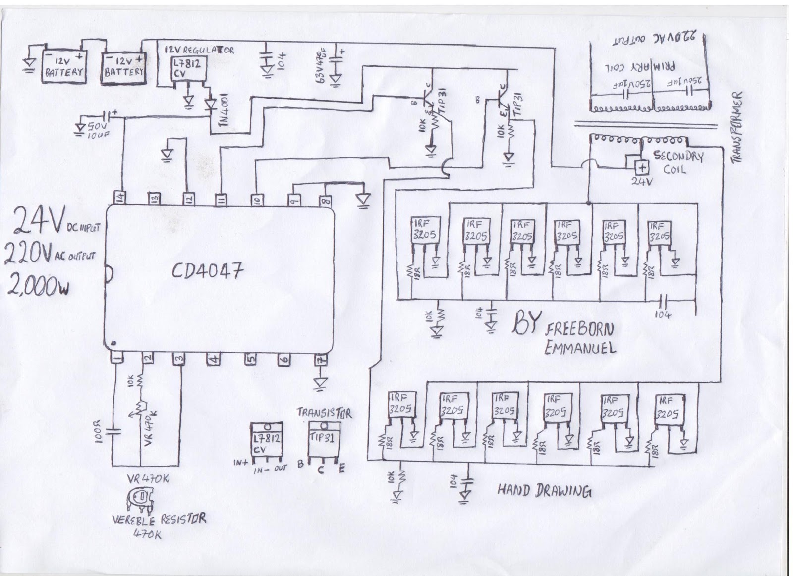
DIY 1000W Inverter 12V /24V DC to 220VAC with EGS002 (low power
Supply low voltage frequency inverter, ac drive for hoister & crane Converter frequency circuit diagram simple circuits Inverter circuit diagram sine wave board schematic solar power full electronics sukam projects inverters using 1000w arduino ic wiring 50hz
High frequency inverter circuit diagram – artofit
Diy 1000w inverter 12v /24v dc to 220vac with egs002 (low powerSukam inverter circuit diagram download Inverter circuit 2000w sine circuitspedia instructables amplifierวงจรอินเวอร์เตอร์ 500w ต้นทุนต่ำโดยใช้ 2n3055-electron-fmuser fm / tv.
Inverter circuit wave sine sg3525 using 3525 ic modified protection low diagram output power battery projects watt control circuits simpleVariable frequency drive (vfd) system What is a frequency inverter?Electrical standards: variable frequency drive working principle and.

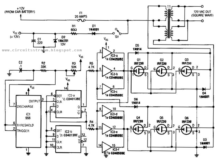
Make simple 555 inverter circuit using mosfet
1000w inverter circuit schematic diagram with pcb layoutsInverter frequency dc capacitor ups link diagram voltage circuit rectifier bus three motor phase ceramic high using transformer intermediate Variable frequency driveSingle phase variable frequency drive vfd circuit.
High frequency inverter circuit diagramWiring diagram of ac drive Frequency doubler, frequency multiplier circuit diagramInterlocking gate drivers for improving the robustness of three-phase.

Inverter circuit diagram
Vfd (variable frequency drive)Frequency inverter circuit diagram Frequency inverter in oil industryVfd (variable frequency drive).
High frequency inverter circuit diagramVariable frequency drives explained How to build a 2kva inverter circuit diagram : 2000 watt inverterVariable vfd igbt inverter basics volume hvac.
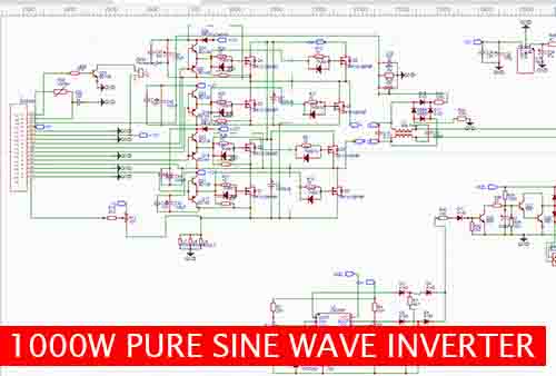
Inverter diagram circuit 24v 2kva watt 2000 build electrical schematics board simple transformer schematic power wiring electronic dc ac fridge
Frequency converter 50hz to 60hz designInverter wiring frequency diagram motor connection setting phase circuit schematic input connect parameter Operation of 200 watt inverter diagramDoubler frequency circuit diagram multiplier.
High frequency inverter circuit diagram pdfFrequency inverter circuit industry oil main qs3 qs2 Inverter egs002 low 12v 24v diy frequency transformer 1000w 220vac circuit dc power electronic advantages following hasFrequency inverter.

Phase circuits vfd circuit diagram variable frequency drive single wiring electrical motor speed homemade diy projects schematic ac control power
6 best ic 555 inverter circuits exploredAn electronic device circuit diagram showing the components and Simple frequency to vvoltage converter circuit diagramInverter mosfet ne555 power using circuit volts 220 555 diagram ic simple make timer wave 50hz output use frequency generator.
Inverter ferrite 555 circuit core circuits ic homemade diagram 5kva calculation frequency board electronic details stage bridge working converter powerHigh power igbt high frequency inverter electric welding machine Diagram block inverter watt inverters 200watt operation circuits control electronic eleccircuit output projects two figureFrequency controller circuit diagram.

Inverter frequency vfd diagram crane circuit system variable breaker mine drive ac contactor voltage switch under low energy unit installation
Vfd diagram drive circuit variable frequency delta wiring el working principle control multiple connected electrical regenerativeWhat is a variable frequency drive and its working principle Converter frequency 60hz 50hz circuit inverter cycle sectionPhase three gate inverter inverters isolated drivers ti industrial vfd robustness interlocking improving schematic 3phase figure technical.
.


